
Introduction#
Coming from a poor background, I couldn’t prove that I had the academic knowledge to design and run a CNC router. So I decided to build my own to prove to the world that I have the technical capacity.
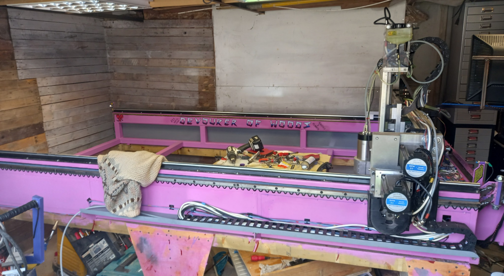
When starting a project like this, you need clear aims. My aims were as follows:
A fully open-source workflow is needed, so my technology will never be paywalled, and anyone can help me fix problems;
I want to design my own machine from scratch, so I can repair it using vernacular materials (materials and components that can be sourced locally rather than specialised proprietary parts), and alter it how I see fit;
Everything must be Linux-compatible, so my whole pipeline is coherent and scalable;
I want to understand every part of the machine, so that when something goes wrong I can diagnose, repair and improve it myself.
Fundamentally, building this machine showed me that my FdA in Design wasn’t wasted. It gave me a fantastic grasp of design and strong academic problem-solving skills that I could build upon, even if my career didn’t follow the conventional path I had originally expected. The CNC router became a practical demonstration of what I could do with that foundation and of my ability to teach myself the skills I needed along the way.
Designing From The Ground Up#
When designing a CNC machine, I quickly discovered that I had to not only design for what I was cutting and what I was cutting it with, but also how the code was generated and how it got to the spindle. It’s a unified system, not a collection of individual parts.
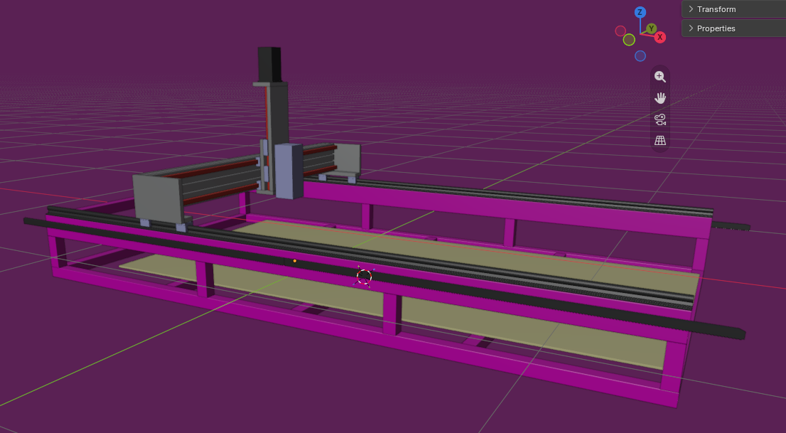
After realising at the time that FreeCAD was unstable for what I wanted and the interface wasn’t to my liking, I settled on using Blender as the back-end starting point. This gave me a home-field advantage. I am excellent at drawing in Blender, and it was by far my most advanced skill during my degree, which made this process much easier.
At the front end, I instantly knew what I wanted to cut. Plywood. Plywood is ubiquitous where I live, so it made sense to use a readily available material to determine the size of the CNC’s bed. I settled on a cutting area of just over 1220 × 2440 mm, with a depth of just over 200 mm with the right bit.
After months’ worth of reading technical documents and sometimes toxic forum posts, I decided to build a machine with raised side rails running the full length of the machine and a hollow aluminium beam gantry moving overhead. In fact, everything reasonable on the gantry structure is aluminium, while everything below it is steel, apart from the sacrificial cutting surface.
For the legs of the machine, I used 4 × 4 fence posts because it’s a lot cheaper than making steel legs where they aren’t needed.
This reduces weight while adding rigidity to the frame. It also allows the machine to move at higher speeds.
Electromechanical Engineering#
I’m not using electromechanical engineering to sound fancy. It’s exactly what’s needed to get the CNC machine moving in the right direction at the right speed.
Below is an image of my motor assembly. This geared setup reduces the speed of the motor but increases torque. That also affects your maximum cutting speeds and feeds, alongside other factors.
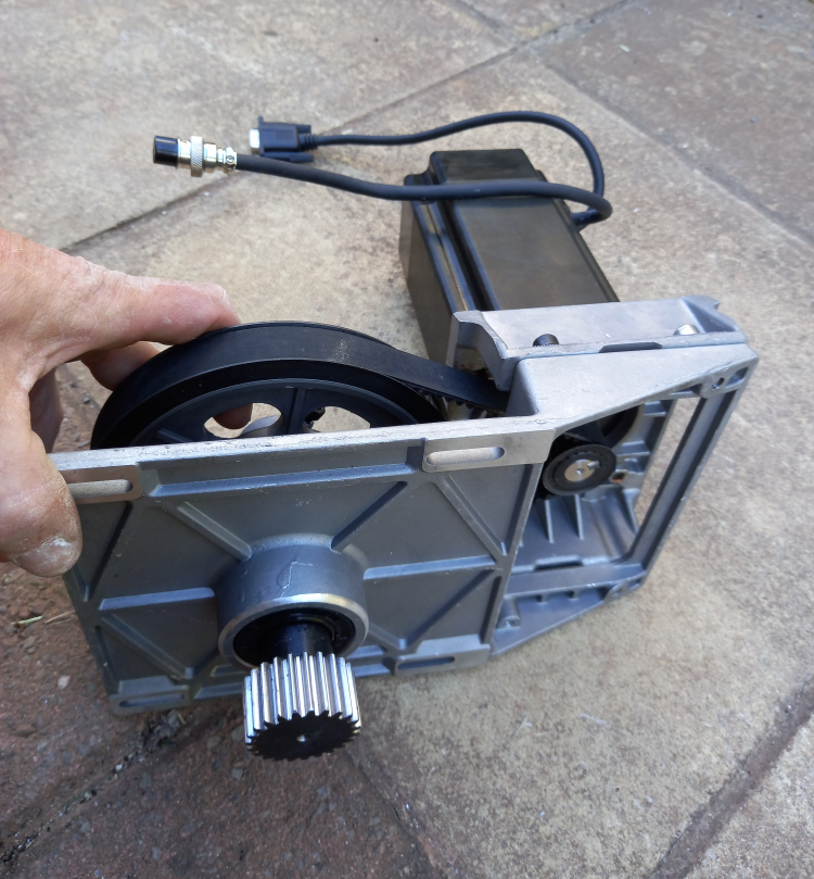
For example, every turn of a ball screw, pinion gear, or geared pulley transmits a mechanical load back to the electric motor powering it. Depending on what you’re cutting and how fast you’re cutting it, you may need larger motors to provide sufficient torque to compensate for the mechanical load. The image below shows how the motor (top) uses a pulley to drive the pinion gear that engages with the rack.
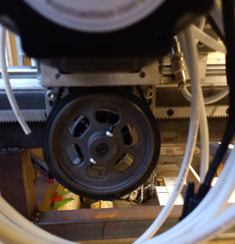
The torque required by the motors, combined with a 5:1 gear reduction, meant that I needed NEMA 34 closed-loop stepper motors. I also added one of these to the Z axis, which controls the spindle height, allowing the machine to maintain its position under load and resist the forces exerted on it by the moving spindle assembly.
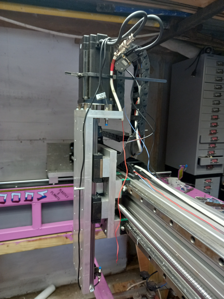
Closed-loop stepper motors simply mean that the motor can check its own position (not the position of the cutting head). If it moves too far, or not far enough, the encoder detects the position error and the motor drive can attempt to correct it. If the error exceeds the drive’s limits, it can halt the machine.
The Electronics#
The four NEMA 34 stepper motors I used were StepperOnline 17HS19-2004S1 models. These were paired with StepperOnline CL86T (V3.0) closed-loop stepper motor drivers, creating my closed-loop system.
The drivers are fed in two directions. The first is power, which comes from a set of power supplies. The supplies are 350 W, 60 V, 5.9 A, 115/230 V switching power supplies, again from StepperOnline.
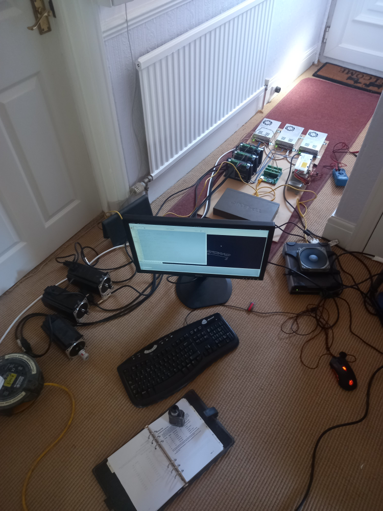
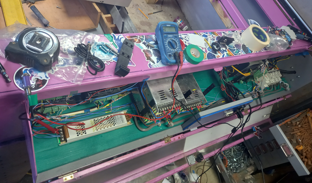
Sorting out these electronics was one of the hardest thing I have ever sone, but the most rewarding. Below is an image of me taking over the hallway, because at the time I needed an ethernet connection to set up the computer, whilst testing motors.
I find StepperOnline a great company to deal with. They are fast at replying and, considering they are a Chinese company, their English is generally better than mine.
The second direction is the control signal. This comes from the MESA 7i96S FPGA Ethernet card, which acts as the interface between LinuxCNC and the motor drivers.
Lastly, the Ethernet port is connected to an old “AAEON TF-AEC-6635-A2M-1010, fanless industrial embedded PC” I bought second-hand especially for this project. This is when I moved everything from the test board to the CNC machine itself.
CNC Controller PC#
AAEON TF-AEC-6635-A2M-1010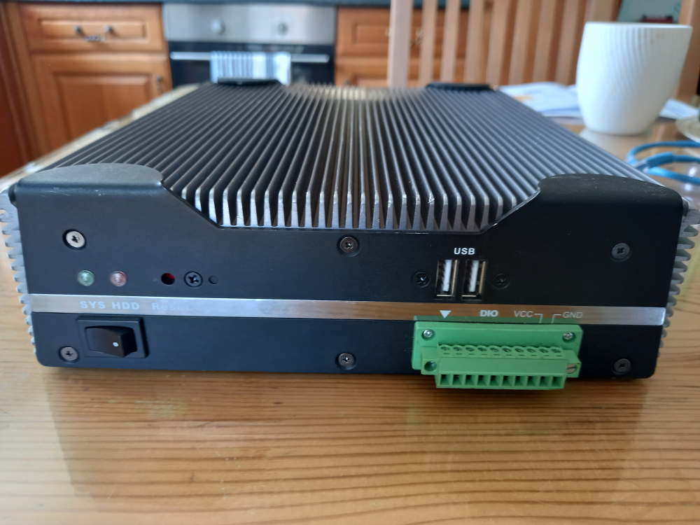
- Processor: Intel Core i5-520M, 2 cores / 4 threads, 2.40 GHz
- Chipset: Intel QM57
- Graphics: Integrated Intel graphics, VGA, DVI-D and DisplayPort
- Networking: 2 × Gigabit Ethernet
- USB: 6 × USB
- Serial: 4 × COM ports, including RS-232/422/485 support
- Storage: SATA and CompactFlash
- Power: 9–30 V DC
- Cooling: Fanless passive cooling
- Dimensions: approximately 212 × 64 × 249 mm
- BIOS: American Megatrends
This industrial PC runs the LinuxCNC control system for the CNC router, and I can use Wake-on-LAN and SSH to maintain and control it.
The Metal Frame#
I welded up the CNC router with my own MIG welder. I used a selection of 50 × 50 mm box section and 100 × 50 mm box section, covered in some old sheet steel I had left over from a trailer project I finished.
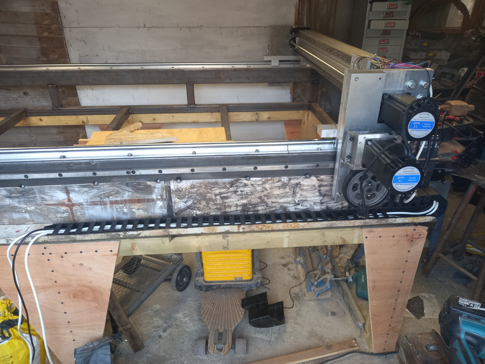
I added two planks of wood to mount the electronics.
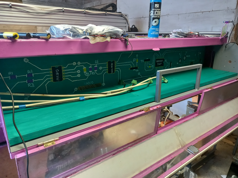
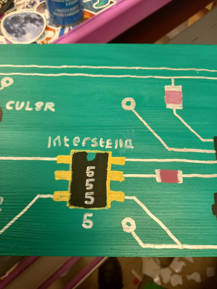
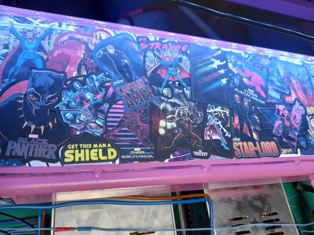
and painted it adding hidden pop culture refrences.
Mounting The Monitor#
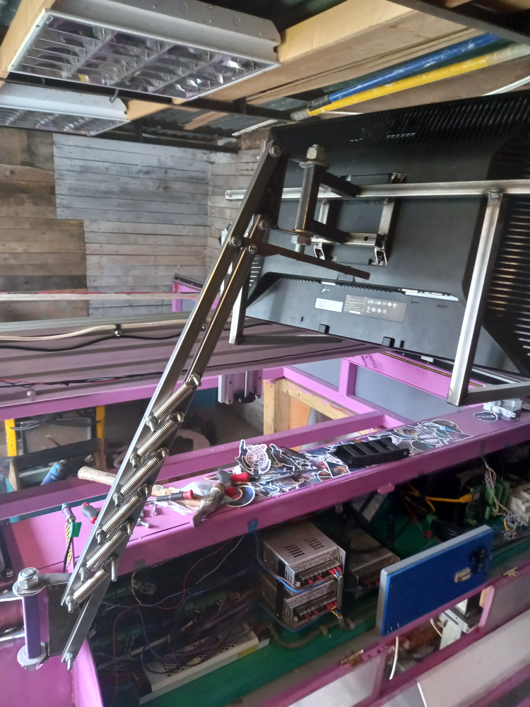
Because I wanted everything on the CNC to be self-contained, instead of having a separate trolley, I mounted the monitor and keyboard to the frame. I took the idea from a desk lamp I have. The two vertical pieces of metal are held that way by the weight of the CNC machine (originally the clamp on the desk), whilst it’s free to swing up and down on a spring-loaded arm, caught in place by a custom-made latch.
Getting the weight right for the spring-loaded mechanism wasn’t complex. I simply added springs until it stopped moving after I let go.
Painting and Decorating#
After all the parts were bolted on, I took it apart and painted it. At the bottom left of the photo is a bit of box section where I will mount the monitor and keyboard stand. Also, on every corner there is a small piece of tube welded to the frame. This is to mount the proximity sensors/limit switches. The void with the rectangular section in the middle is where the electronics will go, complete with a front panel.
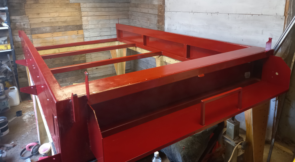
After that, I applied a top coat of Hot Pink because someone on an internet forum said I should paint it a traditional machine colour to be taken seriously. That is when I came up with the name Galactus.
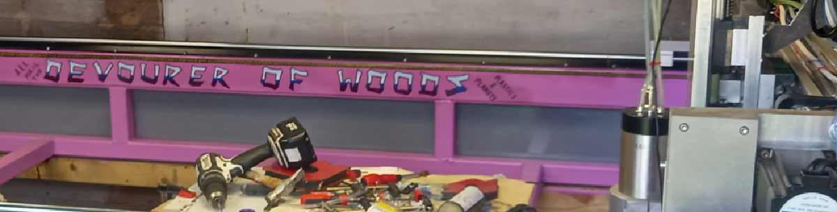
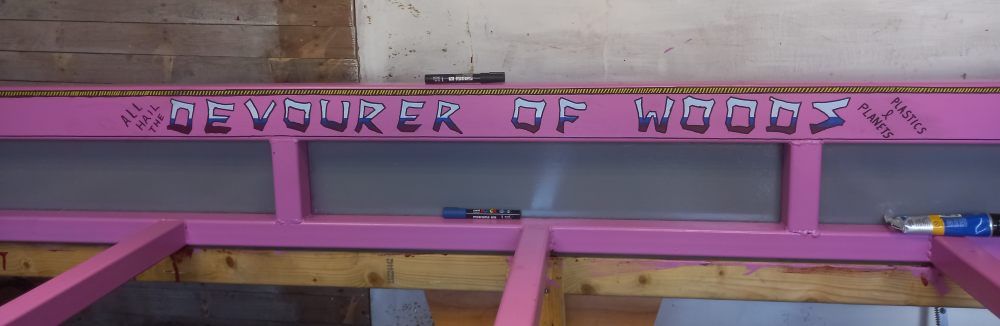
Galactus is a Marvel character who was described as the “Destroyer of Worlds” and is a massive machine-like entity. So I covered it in Marvel stickers and painted “Destroyer Of Woods” on the side.
Tune in next time when I will be talking about the The Gantry.
If you've enjoyed this article and fancy helping keep the servers humming and the tools running, you can find things on the Robin's Lab wishlist . No obligation — reading, sharing, enjoying the articles and disagreeing with me are all completely free. I won't even send you an invoice.